8.8.3.30 IfcRevolvedAreaSolid
8.8.3.30.1 Semantic definition
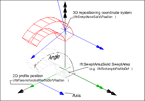
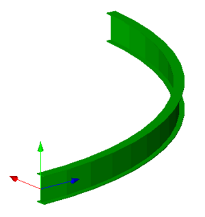
An IfcRevolvedAreaSolid is a solid created by revolving a cross section provided by a profile definition about an axis.
The resulting solid is positioned by the IfcSweptAreaSolid.Position relative to the object coordinate system. If provided, it allows to reposition the revolved solid. If not provided, it defaults to the current object coordinate system. The axis and the cross section shall be in the same plane, prior to any repositioning.
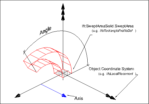
- The profile is defined:
- as a 2D primitive, here IfcRectangleProfileDef, that is placed relative to the xy plane of object coordinate system
- since no 2D profile position coordinate system is provided, here IfcParameterizedProfileDef.Position = NIL, the profile is positioned without transformation into the xy plane of the object coordinate system (by default, centric at 0.,0. with no rotation)
- The resulting swept solid is not repositioned, as no position coordinate system is provided, here IfcSweptAreaSolid.Position = NIL.
The AxisLine can have any orientation within the XY plane, it does not have to be parallel to the y-axis as shown in the illustration.
Informal Propositions
- The AxisLine shall lie in the plane of the SweptArea (as defined at supertype IfcSweptAreaSolid).
- The AxisLine shall not intersect the interior of the SweptArea (as defined at supertype IfcSweptAreaSolid).
- The Angle shall be between 0° and 360°, or 0 and 2π (depending on the unit type for IfcPlaneAngleMeasure).
Texture Use Definition
For side faces, textures are aligned facing upright along the sides with origin at the first point of an arbitrary profile, and following the outer bound of the profile counter-clockwise (as seen from above). For parameterized profiles, the origin is defined at the +Y extent for rounded profiles (having no sharp edge) and the first sharp edge counter-clockwise from the +Y extent for all other profiles. Textures are stretched or repeated on each side along the outer boundary of the profile according to RepeatS. Textures are stretched or repeated on each side along the outermost (longest) revolution path according to RepeatT, where coordinates are compressed towards the axis of revolution.
For top and bottom caps, textures are aligned facing front-to-back, with the origin at the minimum X and Y extent. Textures are stretched or repeated on the top and bottom to the extent of each face according to RepeatS and RepeatT.
For profiles with voids, textures are aligned facing upright along the inner side with origin at the first point of an arbitrary profile, and following the inner bound of the profile clockwise (as seen from above). For parameterized profiles, the origin of inner sides is defined at the +Y extent for rounded profiles (having no sharp edge such as hollow ellipses or rounded rectangles) and the first sharp edge clockwise from the +Y extent for all other profiles.
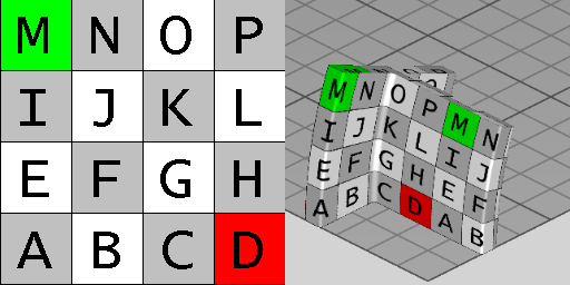
Figure 8.8.3.30.C illustrates default texture mapping with a repeated texture (RepeatS=True and RepeatT=True). The image on the left shows the texture where the S axis points to the right and the T axis points up. The image on the right shows the texture applied to the geometry where the X axis points back to the right, the Y axis points back to the left, and the Z axis points up. For an IfcRevolvedAreaSolid having a profile of IfcTShapeProfileDef and revolved at 22.5 degrees, the side texture coordinate origin is the first corner counter-clockwise from the +Y axis, which equals (-0.5IfcTShapeProfileDef.OverallWidth, +0.5IfcTShapeProfileDef.OverallDepth), while top (end cap) texture coordinates start at (-0.5IfcTShapeProfileDef.OverallWidth, -0.5IfcTShapeProfileDef.OverallDepth).
8.8.3.30.2 Entity inheritance
-
- IfcSolidModel
- IfcAnnotationFillArea
- IfcBooleanResult
- IfcBoundingBox
- IfcCartesianPointList
- IfcCartesianTransformationOperator
- IfcCsgPrimitive3D
- IfcCurve
- IfcDirection
- IfcFaceBasedSurfaceModel
- IfcFillAreaStyleHatching
- IfcFillAreaStyleTiles
- IfcGeometricSet
- IfcHalfSpaceSolid
- IfcLightSource
- IfcPlacement
- IfcPlanarExtent
- IfcPoint
- IfcSectionedSpine
- IfcSegment
- IfcShellBasedSurfaceModel
- IfcSurface
- IfcTessellatedItem
- IfcTextLiteral
- IfcVector
8.8.3.30.3 Attributes
| # | Attribute | Type | Description |
|---|---|---|---|
| IfcRepresentationItem (2) | |||
| LayerAssignment | SET [0:1] OF IfcPresentationLayerAssignment FOR AssignedItems |
Assignment of the representation item to a single or multiple layer(s). The LayerAssignments can override a LayerAssignments of the IfcRepresentation it is used within the list of Items. |
|
| StyledByItem | SET [0:1] OF IfcStyledItem FOR Item |
Reference to the IfcStyledItem that provides presentation information to the representation, e.g. a curve style, including colour and thickness to a geometric curve. |
|
| IfcSolidModel (1) | |||
| * | Dim | IfcDimensionCount |
This attribute is formally derived. The space dimensionality of this class, it is always 3. |
| IfcSweptAreaSolid (2) | |||
| 1 | SweptArea | IfcProfileDef |
The surface defining the area to be swept. It is given as a profile definition within the xy plane of the position coordinate system. |
| 2 | Position | OPTIONAL IfcAxis2Placement3D |
Position coordinate system for the resulting swept solid of the sweeping operation. The position coordinate system allows for re-positioning of the swept solid. If not provided, the swept solid remains within the position as determined by the cross section or by the directrix used for the sweeping operation. |
| Click to show 5 hidden inherited attributes Click to hide 5 inherited attributes | |||
| IfcRevolvedAreaSolid (3) | |||
| 3 | Axis | IfcAxis1Placement |
Axis about which revolution will take place. |
| 4 | Angle | IfcPlaneAngleMeasure |
The angle through which the sweep will be made. This angle is measured from the plane of the swept area provided by the XY plane of the position coordinate system. |
| * | AxisLine | IfcLine |
This attribute is formally derived. The line of the axis of revolution. |
8.8.3.30.4 Formal propositions
| Name | Description |
|---|---|
| AxisDirectionInXY |
The direction of the axis shall be parallel to the XY plane of the position coordinate system. |
|
|
| AxisStartInXY |
The start of the axis shall lie in the XY plane of the position coordinate system. |
|
|
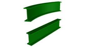
8.8.3.30.5 Examples
8.8.3.30.6 Formal representation
ENTITY IfcRevolvedAreaSolid
 SUPERTYPE OF (ONEOF
	(IfcRevolvedAreaSolidTapered))
 SUBTYPE OF (IfcSweptAreaSolid);
	Axis : IfcAxis1Placement;
	Angle : IfcPlaneAngleMeasure;
 DERIVE
	 AxisLine : IfcLine := IfcRepresentationItem() || IfcGeometricRepresentationItem () || IfcCurve() || IfcLine(Axis.Location,
  IfcRepresentationItem() || IfcGeometricRepresentationItem () || IfcVector(Axis.Z,1.0));
 WHERE
	AxisDirectionInXY : Axis.Z.DirectionRatios[3] = 0.0;
	AxisStartInXY : ('IFC4X3_DEV_9d19c824.IFCCARTESIANPOINT' IN TYPEOF(Axis.Location)) AND (Axis.Location\IfcCartesianPoint.Coordinates[3] = 0.0);
END_ENTITY;