8.18.3.4 IfcGeometricRepresentationContext
8.18.3.4.1 Semantic definition
The IfcGeometricRepresentationContext defines the context that applies to several shape representations of products within a project. It defines the type of the context in which the shape representation is defined, and the numeric precision applicable to the geometric representation items defined in this context. In addition it can be used to offset the project coordinate system from a global point of origin, using the WorldCoordinateSystem attribute. The main representation context may also provide the true north direction, see Figure 8.18.3.4.A.
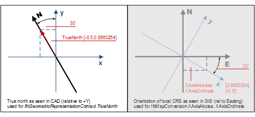
The TrueNorth attribute should be provided, if the y axis of the WorldCoordinateSystem does not point to the global northing. Direction of the true north, or geographic northing direction, relative to the underlying project coordinate system as established by the attribute WorldCoordinateSystem. It is given by a 2 dimensional direction within the xy-plane of the project coordinate system. If not resent, it defaults to [0.,1.] - i.e. the positive Y axis of the project coordinate system equals the geographic northing direction. The direction is provided within project coordinate system and identifies the true north direction.
The "true North as seen in CAD" within Figure 8.18.3.4.A shows the correct interpretation of the TrueNorth direction.
If a conversion to a geographic coordinate system is included by virtue of the HasCoordinateOperation attribute, then the TrueNorth attribute shall be omitted or included only for informational purposes. It shall not be added to any transformation already applied by an IfcCoordinateOperation.
The use of one instance of IfcGeometricRepresentationContext to represent the model (3D) view is mandatory, the use of a second instance of IfcGeometricRepresentationContext to represent the plan (2D) view is optional (but needs to be given, if there are scale dependent plan views), the additional scale or view dependent contexts need to be handled by using the subtype IfcGeometricRepresentationSubContext pointing to the model view (or the plan view) as the ParentContext. See Figure 8.18.3.4.B for an example using geometric representation contexts for 3D and 2D with assigned sub contexts.
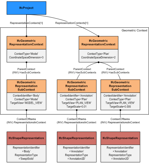
Use of representation contexts defined at IfcProject for 3D model and 2D plan context, including sub context definitions for different target scales. There shall always be a maximum of one geometric representation context for 2D and for 3D coordinate space.
8.18.3.4.2 Entity inheritance
8.18.3.4.3 Attributes
| # | Attribute | Type | Description |
|---|---|---|---|
| IfcRepresentationContext (3) | |||
| 1 | ContextIdentifier | OPTIONAL IfcLabel |
The optional identifier of the representation context as used within a project. |
| 2 | ContextType | OPTIONAL IfcLabel |
The description of the type of a representation context. The supported values for context type are to be specified by implementers agreements. |
| RepresentationsInContext | SET [0:?] OF IfcRepresentation FOR ContextOfItems |
All shape representations that are defined in the same representation context. |
|
| Click to show 3 hidden inherited attributes Click to hide 3 inherited attributes | |||
| IfcGeometricRepresentationContext (6) | |||
| 3 | CoordinateSpaceDimension | IfcDimensionCount |
The integer dimension count of the coordinate space modeled in a geometric representation context. |
| 4 | Precision | OPTIONAL IfcReal |
Value of the model precision for geometric models. It is a double value (REAL), typically in 1E-5 to 1E-8 range, that indicates the tolerance under which two given points are still assumed to be identical. The value can be used e.g. to sets the maximum distance from an edge curve to the underlying face surface in brep models. |
| 5 | WorldCoordinateSystem | IfcAxis2Placement |
Establishment of the engineering coordinate system (often referred to as the world coordinate system in CAD) for all representation contexts used by the project. If an geographic placement is provided using IfcMapConversion then the WorldCoordinateSystem atttibute is used to define the offset between the zero point of the local engineering coordinate system and the geographic reference point to which the IfcMapConversion offset relates. In preferred practise both points (also called "project base point" and "survey point") should be coincidental. However it is possible to offset the geographic reference point from the local zero point. |
| 6 | TrueNorth | OPTIONAL IfcDirection |
Direction of the true north, or geographic northing direction, relative to the underlying project coordinate system. It is given by a 2 dimensional direction within the xy-plane of the project coordinate system. If not present, it defaults to 0. 1., meaning that the positive Y axis of the project coordinate system equals the geographic northing direction. |
| HasSubContexts | SET [0:?] OF IfcGeometricRepresentationSubContext FOR ParentContext |
The set of IfcGeometricRepresentationSubContexts that refer to this IfcGeometricRepresentationContext. |
|
| HasCoordinateOperation | SET [0:1] OF IfcCoordinateOperation FOR SourceCRS |
Indicates conversion between coordinate systems. In particular it refers to an IfcCoordinateOperation between a Geographic map coordinate reference system, and the engineering coordinate system of this construction project. If there is more then one IfcGeometricRepresentationContext provided to the IfcProject then all contexts shall have an identical instance of IfcCoordinateOperation as HasCoordinateOperation referring to the same instance of IfcCoordinateReferenceSystem. |
|
8.18.3.4.4 Formal propositions
| Name | Description |
|---|---|
| North2D |
The TrueNorth direction, if provided, shall be a two-dimensional direction. |
|
|
8.18.3.4.5 Formal representation
ENTITY IfcGeometricRepresentationContext
 SUPERTYPE OF (ONEOF
	(IfcGeometricRepresentationSubContext))
 SUBTYPE OF (IfcRepresentationContext);
	CoordinateSpaceDimension : IfcDimensionCount;
	Precision : OPTIONAL IfcReal;
	WorldCoordinateSystem : IfcAxis2Placement;
	TrueNorth : OPTIONAL IfcDirection;
 INVERSE
	HasSubContexts : SET [0:?] OF IfcGeometricRepresentationSubContext FOR ParentContext;
	HasCoordinateOperation : SET [0:1] OF IfcCoordinateOperation FOR SourceCRS;
 WHERE
	North2D : NOT(EXISTS(TrueNorth)) OR (HIINDEX(TrueNorth.DirectionRatios) = 2);
END_ENTITY;