5.4.3.35 IfcGrid
5.4.3.35.1 Semantic definition
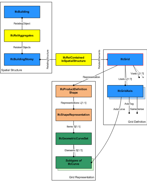
IfcGrid ia a planar design grid defined in 3D space used as an aid in locating structural and design elements. The position of the grid (ObjectPlacement) is defined by a 3D coordinate system (and thereby the design grid can be used in plan, section or in any position relative to the world coordinate system). The position can be relative to the object placement of other products or grids. The XY plane of the 3D coordinate system is used to place the grid axes, which are 2D curves (for example, line, circle, arc, polyline).
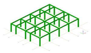
The inherited attributes Name and Description can be used to define a descriptive name of the grid and to indicate the grid's purpose. A grid is defined by (normally) two, or (in case of a triangular grid) three lists of grid axes. The following figures show some examples.
A grid may support a rectangular layout as shown in Figure 5.4.3.35.A, a radial layout as shown in Figure 5.4.3.35.B, or a triangular layout as shown in Figure 5.4.3.35.C.
Informal Propositions
- Grid axes, which are referenced in different lists of axes (UAxes, VAxes, WAxes) shall not be parallel.
- Grid axes should be defined such that there are no two grid axes which intersect twice (see Figure 5.4.3.35.D).
5.4.3.35.2 Entity inheritance
5.4.3.35.3 Attributes
| # | Attribute | Type | Description |
|---|---|---|---|
| IfcRoot (4) | |||
| 1 | GlobalId | IfcGloballyUniqueId |
Assignment of a globally unique identifier within the entire software world. |
| 2 | OwnerHistory | OPTIONAL IfcOwnerHistory |
Assignment of the information about the current ownership of that object, including owning actor, application, local identification and information captured about the recent changes of the object. |
| 3 | Name | OPTIONAL IfcLabel |
An optional name for use by the participating software systems or users. For some subtypes of IfcRoot the insertion of the Name attribute may be required. This would be enforced by a where rule. |
| 4 | Description | OPTIONAL IfcText |
An optional description, provided to exchange informative comments. |
| IfcObjectDefinition (7) | |||
| HasAssignments | SET [0:?] OF IfcRelAssigns FOR RelatedObjects |
Reference to the relationship objects, that assign (by an association relationship) other subtypes of IfcObject to this object instance. Examples are the association to products, processes, controls, resources or groups. |
|
| Nests | SET [0:1] OF IfcRelNests FOR RelatedObjects |
References to the decomposition relationship being a nesting. It determines that this object definition is a part within an ordered whole/part decomposition relationship. An object occurrence or type can only be part of a single decomposition (to allow hierarchical structures only). |
|
| IsNestedBy | SET [0:?] OF IfcRelNests FOR RelatingObject |
References to the decomposition relationship being a nesting. It determines that this object definition is the whole within an ordered whole/part decomposition relationship. An object or object type can be nested by several other objects (occurrences or types). |
|
| HasContext | SET [0:1] OF IfcRelDeclares FOR RelatedDefinitions |
References to the context providing context information such as project unit or representation context. It should only be asserted for the uppermost non-spatial object. |
|
| IsDecomposedBy | SET [0:?] OF IfcRelAggregates FOR RelatingObject |
References to the decomposition relationship being an aggregation. It determines that this object definition is the whole within an unordered whole/part decomposition relationship. An object definition can be aggregated by several other objects (occurrences or parts). |
|
| Decomposes | SET [0:1] OF IfcRelAggregates FOR RelatedObjects |
References to the decomposition relationship being an aggregation. It determines that this object definition is a part within an unordered whole/part decomposition relationship. An object definition can only be part of a single decomposition (to allow hierarchical structures only). |
|
| HasAssociations | SET [0:?] OF IfcRelAssociates FOR RelatedObjects |
Reference to the relationship objects, that associates external references or other resource definitions to the object. Examples are the association to library, documentation or classification. |
|
| IfcObject (5) | |||
| 5 | ObjectType | OPTIONAL IfcLabel |
The type denotes a particular type that indicates the object further. The use has to be established at the level of instantiable subtypes. In particular it holds the user defined type, if the enumeration of the attribute PredefinedType is set to USERDEFINED or when the concrete entity instantiated does not have a PredefinedType attribute. The latter is the case in some exceptional leaf classes and when instantiating IfcBuiltElement directly. |
| IsDeclaredBy | SET [0:1] OF IfcRelDefinesByObject FOR RelatedObjects |
Link to the relationship object pointing to the declaring object that provides the object definitions for this object occurrence. The declaring object has to be part of an object type decomposition. The associated IfcObject, or its subtypes, contains the specific information (as part of a type, or style, definition), that is common to all reflected instances of the declaring IfcObject, or its subtypes. |
|
| Declares | SET [0:?] OF IfcRelDefinesByObject FOR RelatingObject |
Link to the relationship object pointing to the reflected object(s) that receives the object definitions. The reflected object has to be part of an object occurrence decomposition. The associated IfcObject, or its subtypes, provides the specific information (as part of a type, or style, definition), that is common to all reflected instances of the declaring IfcObject, or its subtypes. |
|
| IsTypedBy | SET [0:1] OF IfcRelDefinesByType FOR RelatedObjects |
Set of relationships to the object type that provides the type definitions for this object occurrence. The then associated IfcTypeObject, or its subtypes, contains the specific information (or type, or style), that is common to all instances of IfcObject, or its subtypes, referring to the same type. |
|
| IsDefinedBy | SET [0:?] OF IfcRelDefinesByProperties FOR RelatedObjects |
Set of relationships to property set definitions attached to this object. Those statically or dynamically defined properties contain alphanumeric information content that further defines the object. |
|
| IfcProduct (5) | |||
| 6 | ObjectPlacement | OPTIONAL IfcObjectPlacement |
This establishes the object coordinate system and placement of the product in space. The placement can either be absolute (relative to the world coordinate system), relative (relative to the object placement of another product), or constrained (e.g. relative to grid axes, or to a linear positioning element). The type of placement is determined by the various subtypes of IfcObjectPlacement. An object placement must be provided if a representation is present. |
| 7 | Representation | OPTIONAL IfcProductRepresentation |
Reference to the representations of the product, being either a representation (IfcProductRepresentation) or as a special case of a shape representation (IfcProductDefinitionShape). The product definition shape provides for multiple geometric representations of the shape property of the object within the same object coordinate system, defined by the object placement. |
| ReferencedBy | SET [0:?] OF IfcRelAssignsToProduct FOR RelatingProduct |
Reference to the IfcRelAssignsToProduct relationship, by which other products, processes, controls, resources or actors (as subtypes of IfcObjectDefinition) can be related to this product. |
|
| PositionedRelativeTo | SET [0:?] OF IfcRelPositions FOR RelatedProducts |
Reference to the IfcRelPositions relationship, which defines its relationship with a positioning element. |
|
| ReferencedInStructures | SET [0:?] OF IfcRelReferencedInSpatialStructure FOR RelatedElements |
Reference to the objectified relationship IfcRelReferencedInSpatialStructure may be used to relate a product to one or more spatial structure elements in addition to the one in which it is primarily contained. |
|
| IfcPositioningElement (2) | |||
| ContainedInStructure | SET [0:1] OF IfcRelContainedInSpatialStructure FOR RelatedElements |
Relationship to a spatial structure element, to which the positioning element is primarily associated. |
|
| Positions | SET [0:?] OF IfcRelPositions FOR RelatingPositioningElement |
No description available. |
|
| Click to show 23 hidden inherited attributes Click to hide 23 inherited attributes | |||
| IfcGrid (4) | |||
| 8 | UAxes | LIST [1:?] OF UNIQUE IfcGridAxis |
List of grid axes defining the first row of grid lines. |
| 9 | VAxes | LIST [1:?] OF UNIQUE IfcGridAxis |
List of grid axes defining the second row of grid lines. |
| 10 | WAxes | OPTIONAL LIST [1:?] OF UNIQUE IfcGridAxis |
List of grid axes defining the third row of grid lines. It may be given in the case of a triangular grid. |
| 11 | PredefinedType | OPTIONAL IfcGridTypeEnum |
Predefined types to define the particular type of the grid. |
5.4.3.35.4 Property sets
-
Pset_Risk
- RiskName
- RiskType
- NatureOfRisk
- RiskAssessmentMethodology
- UnmitigatedRiskLikelihood
- UnmitigatedRiskConsequence
- UnmitigatedRiskSignificance
- MitigationPlanned
- MitigatedRiskLikelihood
- MitigatedRiskConsequence
- MitigatedRiskSignificance
- MitigationProposed
- AssociatedProduct
- AssociatedActivity
- AssociatedLocation
-
Pset_Tolerance
- ToleranceDescription
- ToleranceBasis
- OverallTolerance
- HorizontalTolerance
- OrthogonalTolerance
- VerticalTolerance
- PlanarFlatness
- HorizontalFlatness
- ElevationalFlatness
- SideFlatness
- OverallOrthogonality
- HorizontalOrthogonality
- OrthogonalOrthogonality
- VerticalOrthogonality
- OverallStraightness
- HorizontalStraightness
- OrthogonalStraightness
- VerticalStraightness
-
Pset_Uncertainty
- UncertaintyBasis
- UncertaintyDescription
- HorizontalUncertainty
- LinearUncertainty
- OrthogonalUncertainty
- VerticalUncertainty
-
Qto_BodyGeometryValidation
- GrossSurfaceArea
- NetSurfaceArea
- GrossVolume
- NetVolume
- SurfaceGenusBeforeFeatures
- SurfaceGenusAfterFeatures
5.4.3.35.5 Concept usage
| Concept | Usage | Description | |
|---|---|---|---|
| IfcRoot (2) | |||
| Revision Control | General |
Ownership, history, and merge state is captured using IfcOwnerHistory. |
|
| Software Identity | General |
IfcRoot assigns the globally unique ID. In addition, it may also provide a name and description for the concept. |
|
| IfcObjectDefinition (9) | |||
| Classification Association | General |
Any object occurrence or object type can have a reference to a specific classification reference, i.e. to a particular facet within a classification system. |
|
| Aggregation | General |
No description available. |
|
| Approval Association | General |
No description available. |
|
| Constraint Association | General |
No description available. |
|
| Document Association | General |
No description available. |
|
| Library Association | General |
No description available. |
|
| Material Association | General |
No description available. |
|
| Material Single | General |
No description available. |
|
| Nesting | General |
No description available. |
|
| IfcObject (5) | |||
| Object Predefined Type | General |
No description available. |
|
| Object Typing | General |
Any object occurrence can be typed by being assigned to a common object type utilizing this concept. A particular rule, restricting the applicable subtypes of IfcTypeObject that can be assigned, is introduced by overriding this concept at the level of subtypes of IfcObject. This concept can be applied to the following resources: |
|
| Object User Identity | General |
An attribute Name and optionally Description can be used for all subypes of IfcObject. For those subtypes, that have an object type definition, such as IfcBeam - IfcBeamType, the common Name and optionally Description is associated with the object type. |
|
| Property Sets with Override | General |
Any object occurrence can hold property sets, either directly at the object occurrence as element specific property sets, or at the object type, as type property sets. In this case, the properties that are provided to the object occurrence are the combinations of element specific and type properties. In case that the same property (within the same property set) is defined both in occurrence and type properties, the property value of the occurrence property overrides the property value of the type property. |
|
| Assignment to Group | General |
No description available. |
|
| IfcProduct (18) | |||
| Body Geometry | General |
The body or solid model geometric representation of an IfcProduct is typically defined using a Tessellation or Brep. Subtypes may provide recommendations on other representation types that may be used. The following attribute values for the IfcShapeRepresentation holding this geometric representation shall be used:
|
|
| Product Geometric Representation | General |
The geometric representation of any IfcProduct is provided by the IfcProductDefinitionShape allowing multiple geometric representations. It uses the Product Placement concept utilizing IfcLocalPlacement to establish an object coordinate system, in which all geometric representations are founded. |
|
| Product Geometry Colour | General |
No description available. |
|
| Product Geometry Layer | General |
No description available. |
|
| Product Relative Positioning | General |
If the IfcProduct Product Placement is placed relative to an IfcPositioningElement this relationship covers the information on which IfcPositioningElement positions the IfcProduct. |
|
| Product Span Positioning | General |
No description available. |
|
| Box Geometry | General |
No description available. |
|
| CoG Geometry | General |
No description available. |
|
| Mapped Geometry | General |
No description available. |
|
| Object Typing | General |
This concept can be applied to the following resources: |
|
| Product Local Placement | General |
No description available. |
|
| Product Topology Representation | General |
No description available. |
|
| Property Sets for Objects | General |
This concept can be applied to the following resources: |
|
| Quantity Sets | General |
This concept can be applied to the following resources: |
|
| Reference Geometry | General |
No description available. |
|
| Reference SweptSolid Geometry | General |
No description available. |
|
| Reference SweptSolid PolyCurve Geometry | General |
No description available. |
|
| Reference Tessellation Geometry | General |
No description available. |
|
| IfcPositioningElement (1) | |||
| FootPrint Geometry | General |
No description available. |
|
| Click to show 35 hidden inherited concepts Click to hide 35 inherited concepts | |||
| IfcGrid (3) | |||
| Grid Attributes | General |
No description available. |
|
| FootPrint Geometry | General |
The 2D geometric representation of IfcGrid is defined using the 'GeometricCurveSet' geometry. The following attribute values should be inserted
The following constraints apply to the 2D representation:
|
|
| Spatial Containment | General |
This concept can be applied to the following resources: |
|
5.4.3.35.6 Examples
5.4.3.35.7 Formal representation
ENTITY IfcGrid
 SUBTYPE OF (IfcPositioningElement);
	UAxes : LIST [1:?] OF UNIQUE IfcGridAxis;
	VAxes : LIST [1:?] OF UNIQUE IfcGridAxis;
	WAxes : OPTIONAL LIST [1:?] OF UNIQUE IfcGridAxis;
	PredefinedType : OPTIONAL IfcGridTypeEnum;
END_ENTITY;